Top-level projects
Top-level projects are located in gateware/src/top.
Each top-level project has a command-line interface. See the ‘Getting started’ section for how to build and flash these top-level designs.
dsp
Designs demoing parts of the DSP library. Build any of them as follows:
# from `gateware` directory. Show all available example cores -
pdm dsp -h

# build an example core
pdm dsp build --dsp-core nco
- class top.dsp.top.Mirror(*args, src_loc_at=0, **kwargs)
Route audio inputs straight to outputs (in the audio domain). This is the simplest possible core, useful for basic tests.
- class top.dsp.top.QuadNCO(*args, src_loc_at=0, **kwargs)
Audio-rate oscillator (NCO) with internal oversampling. 4 different waveform outputs.
in0: V/oct pitch in1: phase modulation out0: sine out1: saw out2: tri out3: square
- class top.dsp.top.Resampler(*args, src_loc_at=0, **kwargs)
Resample different channels to a different sample rate (and back). Not very musically interesting
- class top.dsp.top.ResonantFilter(*args, src_loc_at=0, **kwargs)
High-, Low-, Bandpass with cutoff & resonance control.
in0: audio in in1: cutoff (0V == off, ~5V == open) in2: resonance (0V == min, ~5V == crazy)
out0: LPF out out1: HPF out out2: BPF out
- class top.dsp.top.DualVCA(*args, src_loc_at=0, **kwargs)
Audio-rate VCA.
- class top.dsp.top.Pitch(*args, src_loc_at=0, **kwargs)
PSRAM-backed pitch shifter with CV-controlled pitch. Grain size is quite large (~250ms) to reduce fluttering.
- class top.dsp.top.Matrix(*args, src_loc_at=0, **kwargs)
Matrix mixer with fixed coefficients.
- class top.dsp.top.DualWaveshaper(*args, src_loc_at=0, **kwargs)
Soft distortion, channel 1/2 inputs, 3 is overdrive gain.
- class top.dsp.top.TouchMixTop(*args, src_loc_at=0, **kwargs)
Matrix mixer, combine touch inputs in interesting ways.
- class top.dsp.top.PSRAMPingPongDelay(*args, src_loc_at=0, **kwargs)
2-channel stereo ping-pong delay, backed by external PSRAM.
2 delay lines are instantiated in isolated slices of the external memory address space. Using external memory allows for much longer delay times whilst using less resources, compared to SRAM-backed delay lines, however on a larger design, you have to be careful that PSRAM-backed delay lines don’t get starved by other PSRAM traffic (i.e video framebuffer operations).
Tiliqua input 0/1 is stereo in, output 0/1 is stereo out.
- class top.dsp.top.SRAMPingPongDelay(*args, src_loc_at=0, **kwargs)
2-channel stereo ping-pong delay, backed by internal SRAM.
Tiliqua input 0/1 is stereo in, output 0/1 is stereo out.
- class top.dsp.top.PSRAMDiffuser(*args, src_loc_at=0, **kwargs)
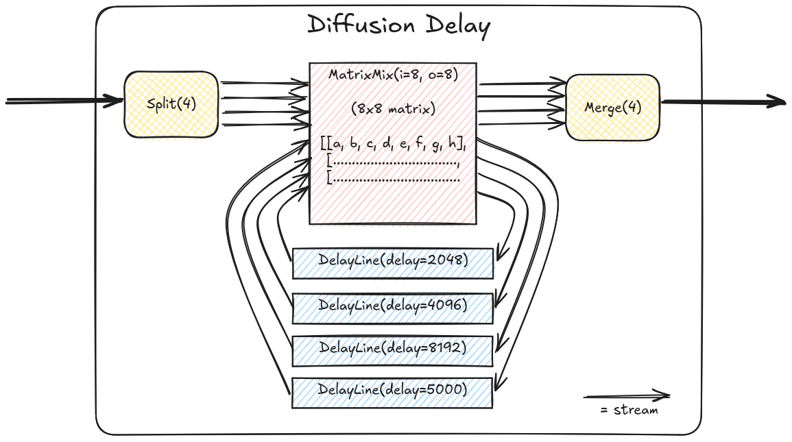
PSRAM-backed 4-channel feedback delay, diffused by a matrix mixer.
A block diagram of the signal flow inside this demo:

All 4 input channels are inputs. All 4 output channels are outputs.
- class top.dsp.top.SRAMDiffuser(*args, src_loc_at=0, **kwargs)
SRAM-backed 4-channel feedback delay, diffused by a matrix mixer.
- class top.dsp.top.PSRAMMultiDiffuser(*args, src_loc_at=0, **kwargs)
Kind of ridiculous 3x chained diffusers (4x4 diffuser into 4x4 diffuser into 4x4 diffuser).
All 4 input channels are inputs. All 4 output channels are outputs.
Be careful with the input amplitude on this one, it clips inside the diffuser multipliers pretty easily and can be a bit unstable.
Sounds pretty close to a REALLY long reverb. A single diffuser suffices for most real audio applications, but this one is a bit crazy :).
Its also useful for stress-testing the memory interface logic.
With 2x PSRAM-backed diffusers that’s 8x simultaneous 48kHz audio streams hitting the PSRAM (4 write streams, 4 read streams). In simulation the PSRAM controller is blocking ~15% of the time. Looking at the traces it seems the cache is bursting twice as often as it really needs to (in theory), so probably tweaking the cache architecture could get the PSRAM bandwidth consumption down considerably.
xbeam
Vectorscope and 4-channel oscilloscope with menu system.
In vectorscope mode, rasterize X/Y (audio channel 0, 1) and color (audio channel 3) to a simulated CRT.
In oscilloscope mode, all 4 input channels are plotted simultaneosly in classic oscilloscope fashion.
polysyn
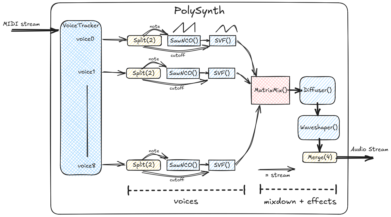
8-voice polyphonic synthesizer with video display and menu system.
The synthesizer can be controlled through touching jacks 0-5 or using a MIDI keyboard through TRS midi. The control source must be selected in the menu system.
In touch mode, the touch magnitude controls the filter envelopes of each voice. In MIDI mode, the velocity of each note as well as the value of the modulation wheel affects the filter envelopes.
Output audio is sent to output channels 2 and 3 (last 2 jacks).
Input jack 0 also controls phase modulation of all oscillators, so you can patch input jack 0 to an LFO for retro-sounding slow vibrato, or to an oscillator for some wierd FM effects.
A block diagram of the core components of this polysynth:

selftest
Collect some information about Tiliqua health, display it on the video output and log it over serial. This is mostly used to check for hardware issues and for bringup.
macro_osc
‘Macro-Oscillator’ runs a downsampled version of the DSP code from a famous Eurorack module (credits below), on a softcore, to demonstrate the compute capabilities available if you do everything in software.
All 24 engines are available for tweaking and patching via the UI. A couple of engines use a bit more compute and may cause the UI to slow down, however you should never get audio glitches. A scope and vectorscope is included and hooked up to the oscillator outputs so you can visualize exactly what the softcore is spitting out.
The original module was designed to run at 48kHz. Here, we instantiate a powerful (rv32imafc) softcore (this one includes an FPU), which is enough to run most engines at ~24kHz-48kHz, however with the video and menu system running simultaneously, it’s necessary to clock this down to 12kHz. Surprisingly, most engines still sound reasonable. The resampling from 12kHz <-> 48kHz is performed in hardware below.
Jack mapping:
In0: frequency modulation
In1: trigger
In2: timbre modulation
In3: morph modulation
Out2: ‘out’ output
Out3: ‘aux’ output
There is quite some heavy compute here and RAM usage, as a result, the firmware and buffers are too big to fit in BRAM. In this demo, the firmware is in memory-mapped SPI flash and the DSP buffers are allocated from external PSRAM.
Credits to Emilie Gillet for the original Plaits module and firmware.
- Credits to Oliver Rockstedt for the Rust port of said firmware:
The Rust port is what is running on this softcore.
usb_audio
4-channel USB2 audio interface, based on LUNA project. Enumerates as a 4-in, 4-out 48kHz sound card.
usb_host
Extremely bare-bones USB MIDI host demo. EXPERIMENTAL.
*WARN* This demo hardwires the VBUS output to ON !!! *WARN*
At the moment this is only used for Tiliqua hardware validation. NOTE: the MIDI USB configuration and endpoint IDs are hard-coded below.
At the moment, all the MIDI traffic is routed to CV outputs according to the existing example (see docstring) in top/dsp:MidiCVTop.
vectorscope_no_soc
CRT / Vectorscope simulator. Rasterizes X/Y (audio channel 0, 1) and color (audio channel 3) to a simulated CRT display, with intensity gradient and afterglow effects.
Simple gateware-only version, this is mostly useful for debugging the memory and video subsystems with an ILA or simulation, as it’s smaller.
See ‘xbeam’ for SoC version of the scope with a menu system.
# for visualizing the color palette
$ pdm colors_vectorscope
- class top.vectorscope_no_soc.top.VectorScopeTop(*args, src_loc_at=0, **kwargs)
Top-level Vectorscope design.
- top.vectorscope_no_soc.top.colors()
Render image of intensity/color palette used internally by FramebufferPHY. This is useful for quickly tweaking it.