[Devlog 1] EMC Adventures
Note
Thanks for dropping by! Tiliqua is an open-source project (see Funding & Open Source ). Feel free to join the discussion (see Community) or join our mailing list.
What a crazy last couple of months! I’ve been super busy bringing up the Tiliqua R4 (latest) hardware revision and getting it ready for production. The trickiest aspect was getting it through EMC testing, so this will be our focus today.
New Features
Before we dive deep into EMC, a quickfire list of unrelated wins from the last couple months:
R4 Hardware Diagrams: I put together some detailed hardware diagrams of how the different bits of Tiliqua connect together, you can find them under Electrical Design.
Self-calibration: Tiliqua can now semi-automatically calibrate its own CODEC for better control voltage tracking, you’ll find the gruesome details under Calibration.
Bitstream Archives: The format used for sharing and flashing user bitstreams is implemented and relatively stable now, this means you can share a single file which contains everything a project needs (bitstream, firmware, images, description of the contents). Gruesome details under Bootloader.
Parallel builds: It’s now possible to build all the Tiliqua projects simultaneously, which reduces the build time from about 15min for all projects (about 30 bitstreams) to about 5min on my machine. Try this out with gateware/scripts/build_bitstreams_soc.sh!
Menu system refactor: The Tiliqua menu system has been completely rewritten , which should make it much easier to modify it for your own purposes. I plan to write a short tutorial on how this works soon.
In this update
R4 Hardware & EMC: A lot of work went into getting Tiliqua ready for EMC testing, I’ll go through some lessons learned.
Dynamic Clocking: The latest revision adds an external PLL, useful for EMC (spread spectrum) and dynamic resolution switching. We’ll cover this below.
100% Amaranth: Until recently there were some core Tiliqua components (especially audio CODEC initialization, calibration, the video subsystem) that were still re-using Verilog cores. These are now all removed and ported to Amaranth, which should make the codebase easier to understand!
CE and FCC

Any kind of electronic product sold in the EU must have evidence that it meets the requirements for a CE mark, in the US the (almost) equivalent mark is FCC. For a eurorack module like Tiliqua, there 2 most interesting sets of standards:
EMC: There are hundreds of standards related to EMC (Electromagnetic Compliance: radio emissions and static discharge), however only a few are relevant to a low-voltage musical instrument like Tiliqua.
RoHS: Restrictions on Hazardous Substances - this means that we are not using any nasty chemicals or leaded solder for example. Usually no testing is required to meet this, you just collect documentation for every single component and assembly step of your product and make sure that each part meets RoHS.
If you go to a test lab they will tell you exactly which standards are relevant to your product. For something like a Eurorack Module, it’s the emissions requirements (radiated and tolerated radio emissions) and ESD immunity (simulated sparks from fingers) that are the most challenging.
The Setup
Example system
At a test lab, you are expected to bring a self-contained test system with your product in use. This means in the end it is not just your Eurorack module that must meet EMC, but the entire system, including the mains cable!
For Tiliqua’s testing I put together a small system like this, including not just the Tiliqua but also a screen module, display cable, headphone interface and so on:
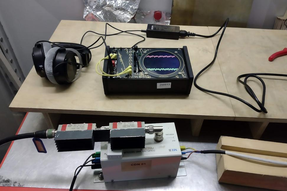
Small example system with headphones and mains adapter in the professional test lab.
The other modules, mains adapter, case, and DC-DC converters inside the case will all affect the test result. So, if you’re going to a test lab for the first time, best to bring spares to swap out for each part.
Pre-test chamber
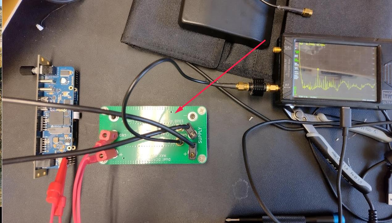
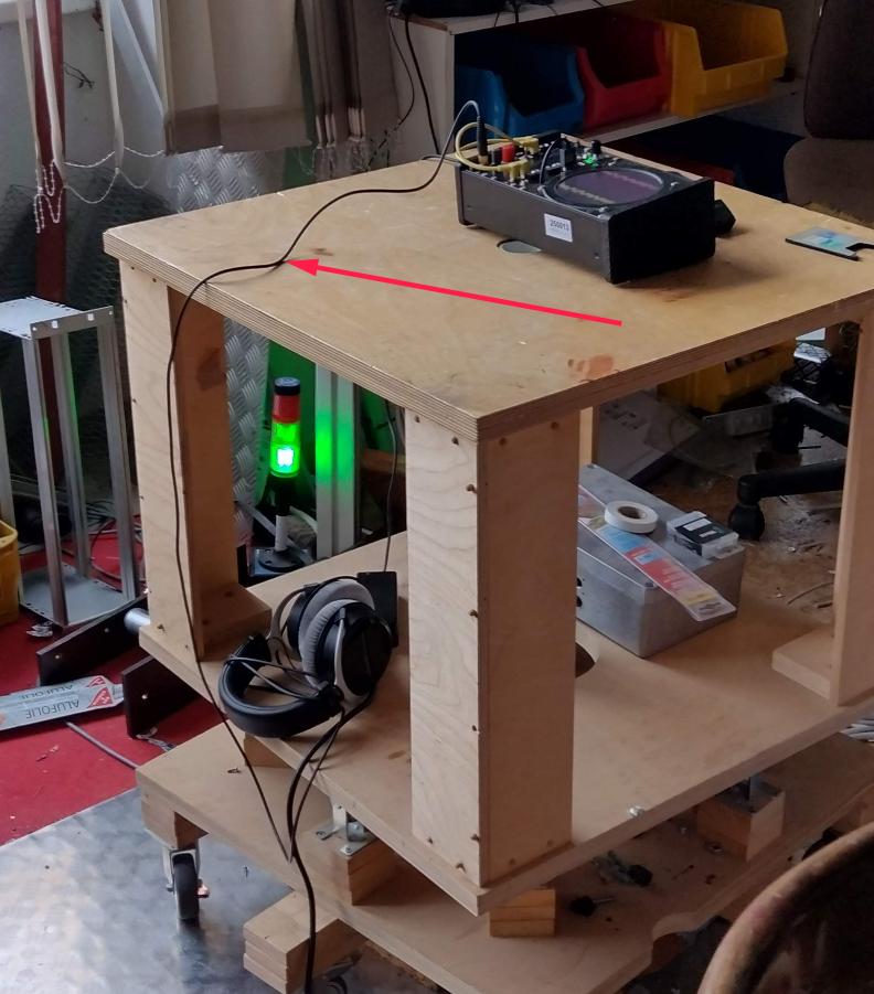
Time at a test lab can be expensive. To save time and money, I built a small EMC test chamber using a slighty modified version of the open-source design you’ll find here. Here’s a picture of my build:
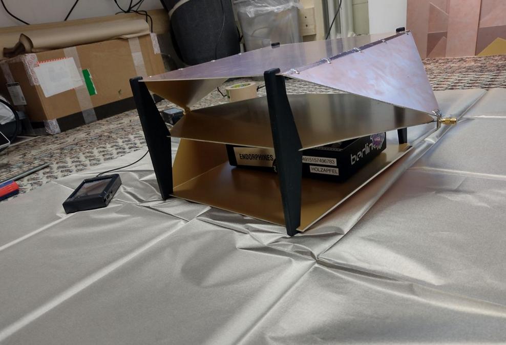
Homebrew TEM cell with TinySA pro and example system inside it.
The chamber is called a “TEM cell”, and you can visualize it like an oversized transmission line - a huge coax cable, which you can put your device into to take broadband measurements. A chamber like this is even allowed as an official measurement method (if you get a much more expensive and calibrated one!).
Spectrum Analyzer
For a cheap spectrum analyzer, I decided to use a TinySA Pro.
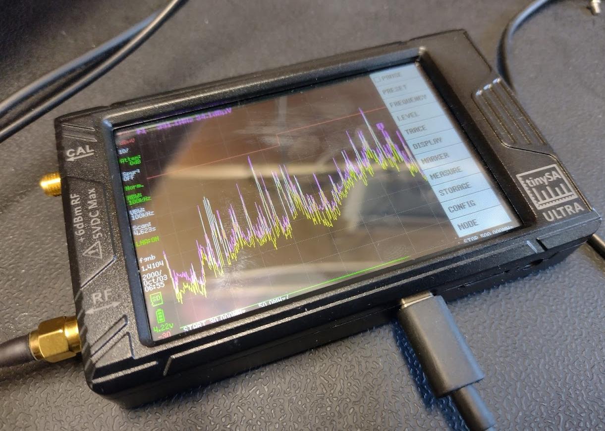
With a TEM cell, there are tables you can use to convert measurements from a cell like this into (rough) far-field measurements, to get an idea of whether you would pass the ‘real’ test or not. You can find lots of details in Petteri Aimonen’s repository.
In my case, I used the TinySA preset found here to check my own measurements against the rough EMC standard thresholds. This results in a nice red ‘fail line’ that is helpful to identify the problematic areas (you can see the red line in the photo above).
Note: I discovered the preset above requires firmware version v1.4104 to work properly, you might want to downgrade to that firmware version in order to use the preset
Dodgy sniffer probe
To help localize the source of radio noise, I put together a super-dodgy sniffer probe using a couple of enamel wire loops:
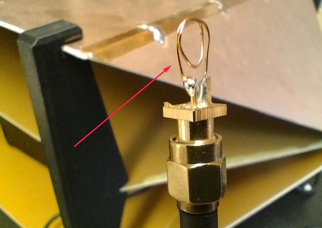
In the end, this probe did not end up being very useful, it worked, but often seemed to point at an area of the board that had nothing to do with the source of the noise. So I’d strongly lean toward just using a TEM cell, the sniffer probe did not help much.
LISN
For measuring conducted noise (noise travelling back up the eurorack power cable), I built a small LISN (line impedance stabilization network) which is used to measure the amount of conducted noise (i.e emitted on the power supply cables). You can build one yourself following the open-source design found here. It looks like this:
Pre-testing: Findings
Fail!
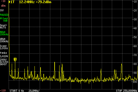
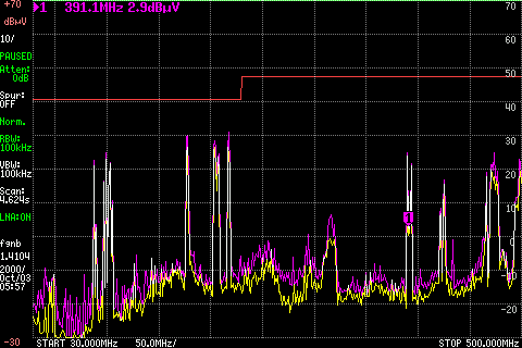
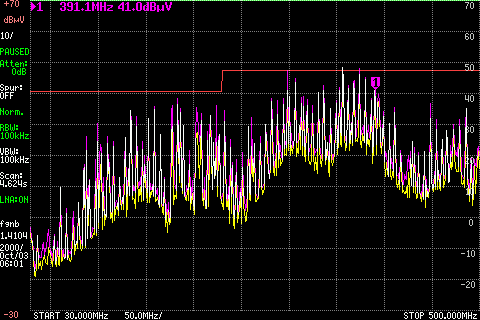
On first measuring Tiliqua R2, things did not look so great. In the TEM cell, radiated emissions looked like this:
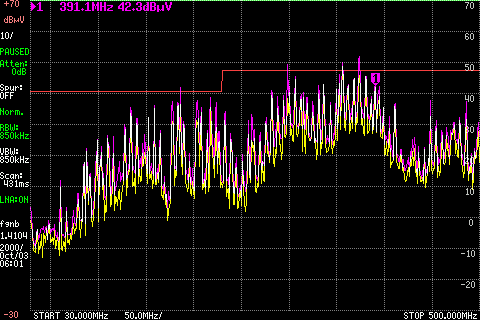
Gross failures, mostly at harmonics of the audio master clock (12.288MHz) and the video master clock (37.4MHz in this case). Conducted emissions with the LISN were not much better:
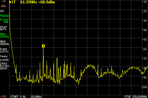
For conducted emissions, our limit is roughly -40dBm. As we measure worse than -60dBm with a 17dB attenuation in-line, this is dangerously close to the limit.
Note
In a eurorack system, there is a bus board and mains adapter between our module and the rest of the world, so likely the conducted noise would not be visible at the mains (and we wouldn’t fail at a test lab), but it’s still good to fix this so we don’t conduct power-supply noise over to other modules in the system and degrade their audio performance.
Clearly, some work had to be done. But where to start?
Learning 1: SMPS input filtering
At the low end of our LISN plot, you can see some spikes and a wideband slice of spectrum suspiciously close to the switching frequency of the +5V switchmode regulator.
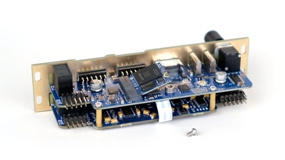
To address this, I added some extra input filtering on the +12V ingress, and then completely re-routed the entire SMPS section, using more polygons and being careful to keep all paths low-inductance. Here’s a comparison of the routing on R2 vs. R4 in this section:
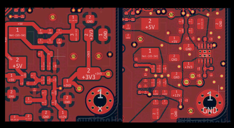
Left: old routing (R2). Right: new routing (R4)
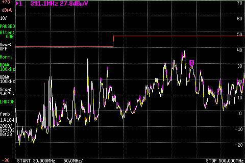
This made quite a dramatic difference. After this change, the conducted noise looks like this (peaks are around 20dB lower than before!):
Learning 2: FPGA drive strengths, series resistors
In our initial radiated emissions plot, at various harmonics of 12.288MHz (audio master clock) and of 37.1MHz (video master clock), you can notice a bunch of emissions.
To address these, I tried to reduce the FPGA pad drive strength as follows:
Reducing pad drive strength in Amaranth platform declaration.
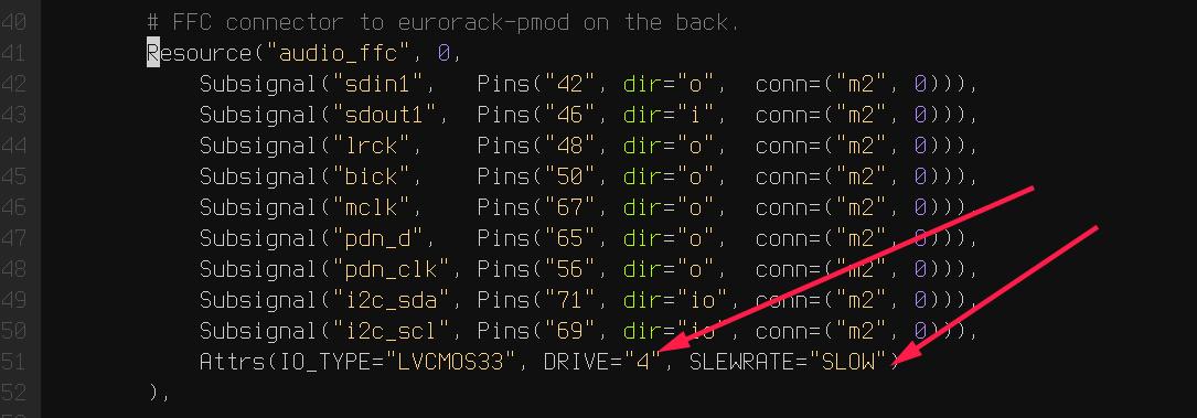
This improved things, but we were still way over the limit. So on Tiliqua R3 I tried adding some extra series resistors on the audio clock/data lines for reduced slew rate:
Series 33R resistors on audio clock/data lines.
These 2 changes got us almost under the limit line. But almost = risky. More work was needed.
Learning 3: Split ground planes
Tiliqua’s audio board uses split ground planes - that is, the analog and digital grounds are isolated with inductors. This is recommended in the CODEC datasheet, however there is some disagreement in the engineering community as to when it harms products vs. when it helps them.
One disadvantage of this approach is that it can negatively impact EMC - if anything couples to the isolated ground plane, it can resonate as an antenna. Turns out, this was exactly what was causing most of the emissions at 12.288MHz harmonics (master audio clock).
As soon as I shorted the isolated analog ground plane to Tiliqua’s metal binding stubs:
The emissions from 12.288MHz harmonics got almost completely squashed! Of course, I think performed a lot of testing to make sure the audio quality did not suffer, and suprisingly it made no difference. So this change was here to stay.
Learning 4: Spread Spectrum
Haunted by the above lessons and to make absolutely sure we would pass in the real test lab, I decided to add another EMC mitigation to Tiliqua R4 - an external spread-spectrum PLL. This allows the FPGA to have clocks which are modulated by some small percent (say 0.1% to 1% or so) at a low frequency (30kHz in our case). The consequence is that the energy in our harmonics is ‘spread out’ across the band, reducing the peak amplitude.
To demonstrate this effect, here is 2 captures, Tiliqua R4 with 2 different bitstreams, one configured with spread-spectrum at 0.1% and one with spread-spectrum at 1%:
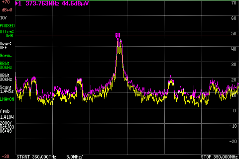
10th harmonic of video master clock with 0.1% spread-spectrum
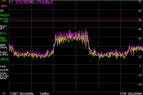
10th harmonic of video master clock at 1% spread-spectrum
It’s not a magic bullet, but definitely makes a difference. Here you see a reduction in the peak amplitude of around 10dB.
This is a feature supported internally by some modern FPGA families, but the ECP5 does not have this feature (nor does any FPGA supported by the open-source FPGA tool flow, as far as we know). So we are essentially relying on the ability of the ECP5’s internal PLL to lock onto a slowly frequency-modulating external PLL. In theory, this should depend on the ECP5 PLL’s loop bandwidth as to what modulation depth should work, which is unfortunately undocumented. Fortunately, this arrangement seems to work fine in my testing.
Distraction: SI5351 Driver and Dynamic Clocking
EMC was not the only reason I decided to add an external PLL, there are 2 more reasons this made a lot of sense for Tiliqua:
The ECP5-25 only has 2 built-in PLLs. This means we can’t have separate PLLs for USB/RAM/audio/video, and means that we have to sacrifice either the accuracy of the audio or video clocks. Undesirable. An extra external PLL means we don’t have to make this compromise.
The ECP5’s internal PLLs cannot be reprogrammed at runtime. This means that the display resolution or audio clocks are fixed after a bitstream has started. With an external PLL, this restriction is lifted. For tiliqua, dynamic resolution switching is a crucial feature, especially as we plan to distribute an optional screen with custom timings. Tiliqua should be able to detect which screen it is attached to and choose its resolution accordingly.
Getting the external PLL to work was not trivial. I had to:
Make sure the si5351 was routed to the correct ECP5 pins (that is, they can be used as a PLL lock source)
Write a driver for the si5351 spread-spectrum capabilities.
Rework the Tiliqua clock tree / gateware so that the asynchronous external clocks generate internal resets and can drive internal signals appropriately.
The si5351 Rust driver (and test cases I added) was based on an open-source driver that I heavily modified such that it can support spread-spectrum configuration and more fine-grained divider settings. You can find my implementation here (it was based on this open source driver that had no spread-spectrum support and no test cases).
I won’t go into more details here, but suffice it to say, if you build a bitstream for Tiliqua R4 now, all this is transparent to you, and you’ll see a nice printout of the resulting clock tree:
┌─────────────[tiliqua-mobo]──────────────────────────────[soldiercrab]────────────┐
│                                          ┊[48MHz OSC]                            │
│                                          ┊└─>[ECP5 PLL]─┐                        │
│                                          ┊              ├>[sync]     60.0000 MHz │
│                                          ┊              ├>[usb]      60.0000 MHz │
│                                          ┊              └>[fast]    120.0000 MHz │
│ [25MHz OSC]─┐                            ┊                                       │
│             └>[si5351 PLL]─┐             ┊                                       │
│                (dynamic)   ├>[expll_clk0]────────────────>[audio]    12.2880 MHz │
│                            └>[expll_clk1]─>[ECP5 PLL]──┐                         │
│                                          ┊             ├─>[dvi]      74.2500 MHz │
│                                          ┊             └─>[dvi5x]   371.2500 MHz │
└──────────────────────────────────────────────────────────────────────────────────┘
This gives you a picture of how all the oscillators and PLLs both inside the FPGA SoM (soldiercrab) and on the Tiliqua motherboard fit together. Most clocks go through an internal ECP5 PLL, except the audio clock, which is routed straight to the fabric.
The dynamic clock tree settings get saved into the bitstream manifest (describing user bitstreams), so the bootloader can dynamically configure the external PLL based on what any particular user bitstream wants.
Lab-testing: Findings
To see the effect of applying all the above changes, here’s a control (empty chamber), before (R2 hardware) and after (R4 hardware) comparison:
Control (empty chamber)
Tiliqua R2 (none of the above learnings applied)
Tiliqua R4 (all of the above learnings applied)
Interestingly, in these plots it is the 300-400MHz region that seems the ‘worst’, however, as we’ll see later, in the real test lab this region was not problematic at all and in fact the 100-200MHz region was more critical, likely due to coupling into the long headphone cable.
Anyway, after all this effort, it was finally time to take Tiliqua to an EMC test lab! To spoil the result, we passed! But it was not without hiccups.
Learning 5: Long cables
One thing that surprised us was how much the headphone cables going into our Eurorack system were affecting the results. It did not bring us over the limit lines (fortunately), but shortening or lengthening the headphone cable made quite a difference to the radiated emissions.
So, be careful with this. In theory, your device should work with any sane length of headphone cable, but if you want to be more certain that things will go well, it might be safer to use something shorter than the 3 meter headphone cable I was using. 3 meters is right in that 100-200MHz resonance where we were close to failing with EMC.
Additionally, long cables are impossible to simulate with a small test chamber (or custom TEM cell like we have).
Learning 6: ESD is no joke
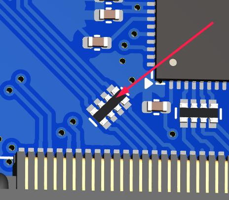
Part of CE testing involves zapping the DUT with an ESD gun. I was especially scared of this given Tiliqua has touch-sensitive jacks where we have the pins of a touch IC exposed to the outside world. Fortunately, I followed Cypress’ recommendations of having a large series resistance to the touch pads, which is supposed to mitigate any ESD frying the touch IC. Normally, adding TVS diodes is a no-brainer for this, but since they add extra capacitance, my fear was that they would negatively effect the touch sensing capabilities.
Surprisingly, however, I discovered that zapping the touchpads with extremely high voltage (i.e. a bit above the standard), the touch sensors would momentarily stop working. After some investigation, I discovered the zap was actually erasing the NVM (non-volatile memory) in the touch IC, the Tiliqua firmware was then detecting this and reprogramming the NVM.
So: be prepared. Add watchdogs to your code. ESD is no joke.
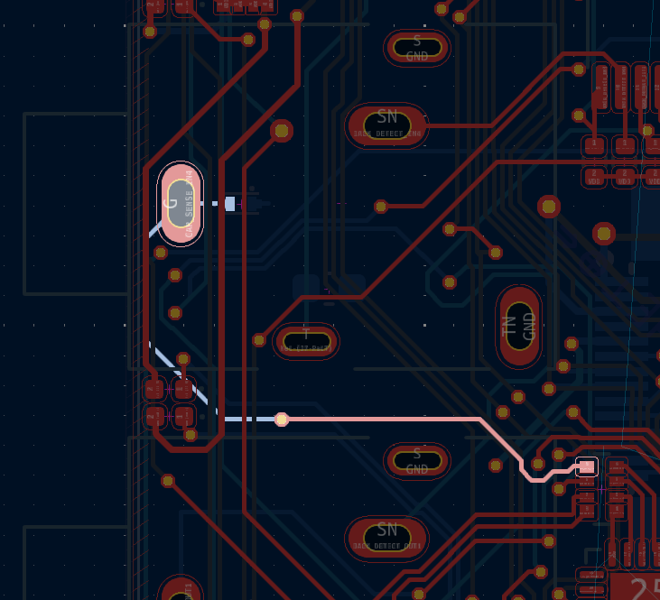
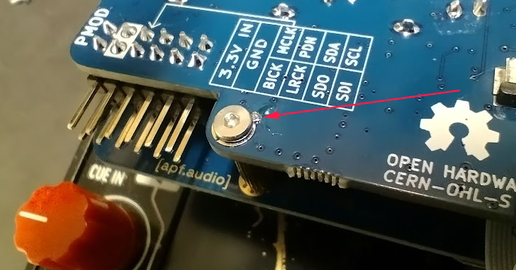
Routing of one of the touch pads through a series resistor
Learning 7: TEM cell vs. real far-field measurements
Because all our pre-testing was in a custom-built TEM cell, I found it interesting to compare the spectrum from our “super-cheap” option with the real thing. In general, we noticed the ‘real’ measurements were about 5-10dB lower in the 300MHz+ region than the TEM cell, but in the 100-200MHz region, the real measurements were about 5-10dB higher than the TEM cell (!). I think the reasons are:
The long headphone cable, which couldn’t be contained inside the TEM cell.
The Eurorack case is a bit too big for this size of TEM cell. Ideally our chamber would be larger.
Imperfections in the TEM cell construction itself.
(Note: I am not sure if I am allowed to publish the lab measurements here, hence the quantitative description of the differences in plots)
EMC: Conclusion
Even though our cheap pre-compliance chamber was not so accurate, it allowed us to figure out which parts of the design needed changes early and squashed the need for doing a second visit.
Tiliqua R4 is now, to our knowledge, EMC compliant. Although this was a LOT of effort, we are confident that all the changes will result in a more robust instrument that stands the test of time, and doesn’t interfere with anything else in your rack.
Bonus: New Amaranth Cores!
We’re happy to report that we’ve finally finished porting all remaining verilog to Amaranth! This will hopefully decrease the learning curve when getting started with this project. Specifically, we rewrote the following:
The audio I2S controller gateware and online sample calibration module (link to PR 82)
The I2C controller gateware for all I2C peripherals on the audio board (LEDs, jack detect, touch detect, codec init) (link to PR)
The display serializer (tmds) and video generator (link to PR 89)
As a result of this rewrite we’re also using a few percent less area of the ECP5. So more space for other things!
Note: Our CPU is as of now the only non-amaranth component (SpinalHDL), however VexRiscv has proven faster and has better area usage than any other core we could find. For this reason, we plan to stick to VexRiscv for the CPU (and perhaps VexiiRiscv in a few monts).
Bonus: Crowd Supply & Trade Tariffs
Obviously everyone in our industry is trying to figure out what to do with the ongoing trade war. For us, our plan was always to launch through CrowdSupply. But with these tariffs, this would imply an undesired price hike. We’re currently talking to Crowd Supply to see what our options are here.
If we launch through Crowd Supply, EU customers (and me of course) would have to eat the cost of US tariffs and then potentially any reciprocal tariffs the EU may set up - which makes zero sense as this is a project centered in the EU. I’m currently working hard to figure out what the best path forward is here and will provide an update once I have more information.
Acknowledgements & further reading
Massive thanks to NLnet for supporting this project (Funding & Open Source).
Petteri Aimonen’s open-source TEM cell design saved loads of time and worked great.
bvernaux’ open-source LISN design saved lots of time and worked great.
Mutable Instruments also has a nice practical overview of the steps involved in EMC certification of Eurorack modules.