Tiliqua Module [TLQ-MODULE]
Tiliqua is shipped with a bunch of example bitstreams already flashed to it. So, to get started, all you need to do is connect the Eurorack +/- 12V ribbon cable, connect a screen, and then switch the Eurorack power on.
Warning
I recommend only plugging or unplugging the display, power, or expansion headers while your system is OFF. All other TRS jacks / USB connectors are fine to hotplug!
Connecting Power
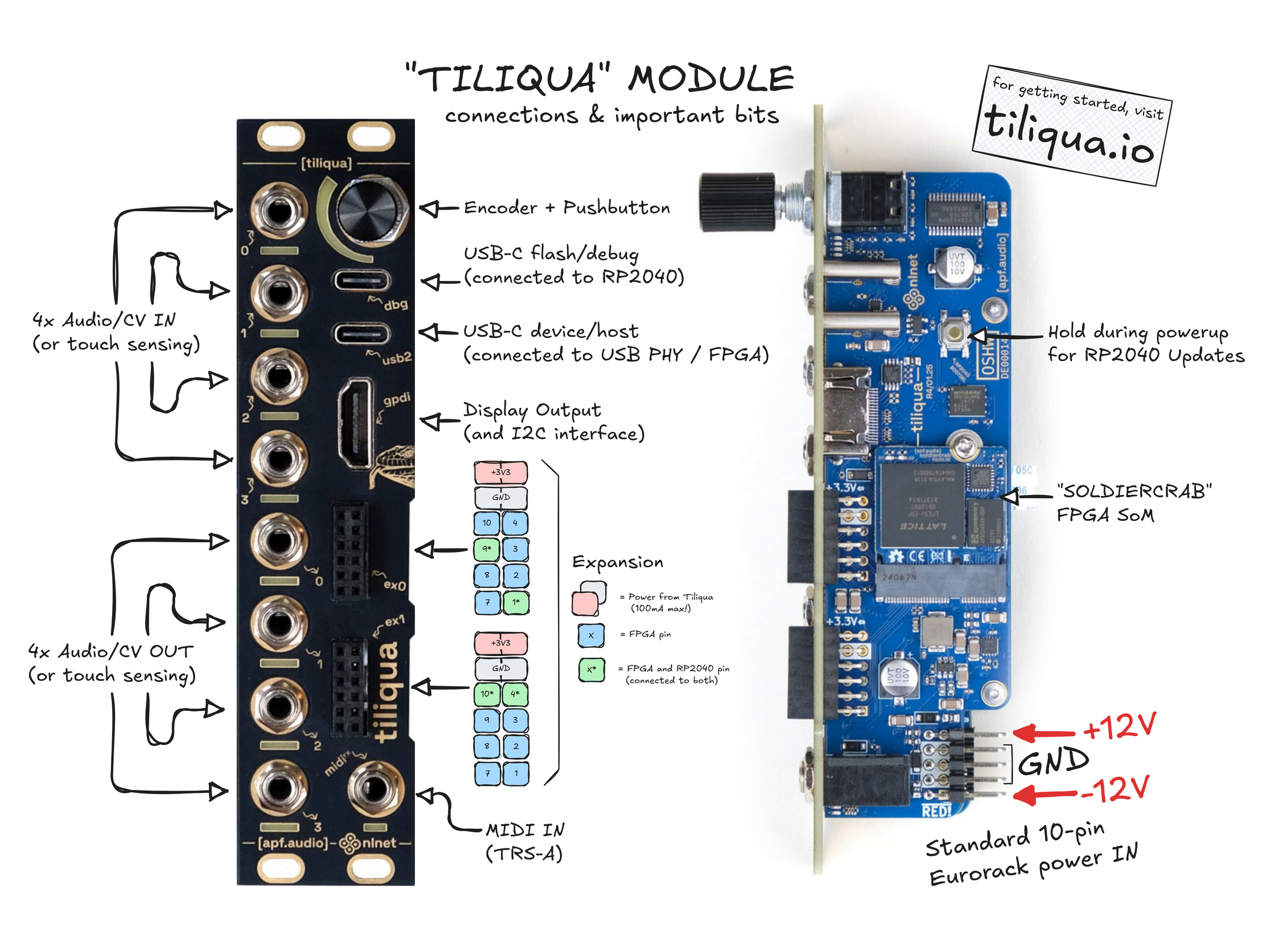
To power Tiliqua, you only need to connect the 16-pin Eurorack power input (+/- 12V) which, out of the box, is already attached to Tiliqua in the correct orientation.
Note
Tiliqua comes with a rainbow power cable rather than a boring gray one. The connector is keyed correctly and the BROWN wire is the -12V wire. RED is still closest to -12V like on a standard gray one. Nothing bad will happen if you accidentally connect it backwards (on the 10-pin side), as Tiliqua has input diodes and fuses.
Connecting a Display
Any standard monitor or projector (or our TLQ-SCREEN module) should work fine as a display for Tiliqua. In general, Tiliqua tries to use the native resolution of any attached screen. However, if the native resolution is higher than 1280x720p60, or no screen is connected at all, we always emit a display signal at 1280x720p60 as a fallback - as the vast majority of screens support this resolution.
Bootloader
After powering on your system, you will be greeted by the bootloader screen:
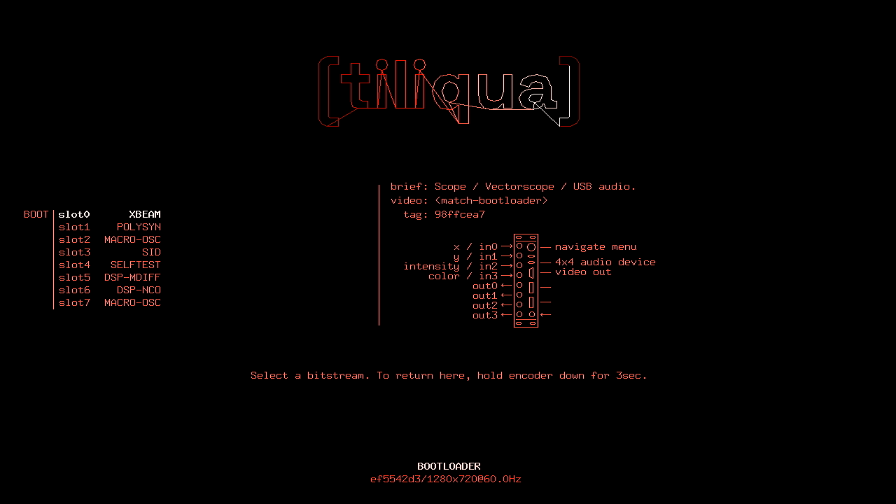
From here, you can use the encoder to select one of 8 slots. As each slot is highlighted, the I/O mapping of each jack and plug is pictured on the right. You will notice some bitstreams have USB, some don’t, some have a display output and others don’t (like the audio-only bitstreams).
To reboot into a selected bitstream, just press the encoder button. Once you’re in a bitstream, you can always hold the encoder button down for 3sec (long press) to mute Tiliqua and re-enter the bootloader.
Note
At the moment, the screen resolution and/or any screen hotplugs are only detected in the bootloader. This is not a hardware limitation, but it does mean that for now you always need to be in the bootloader to change screen resolutions. The current resolution is displayed at the bottom of the bootloader screen.
In general, bitstreams will show video: <match-bootloader> if they are able to inherit the resolution automatically detected by the bootloader. If a bitstream only supports a static mode, you will see something like video: 1280x720p60. If a bitstream does not have any video output, you will see video: <none>.
Menu / Help system
In theory, each user bitstream could have a completely different UI. For now though, most bitstreams that have a display output and are shipped with Tiliqua follow the same menu UI. That is:
Each bitstream has multiple ‘pages’, where the first page is a ‘HELP’ page.
Rotating the encoder allows you to select a different menu option or the current page name.
If the current page name is selected, pressing the encoder will toggle between modifying the current page or not, rotating it will switch to a different page.
If normal option is selected, pressing the encoder will toggle between modifying the value or not, rotating it will increase or decrease the value.
In this way, you can access one of many pages and modify one of many options on each page with the single encoder.
If no option is selected for modification and we are not on the help page, the UI will disappear after some time (useful for generating visualizations).
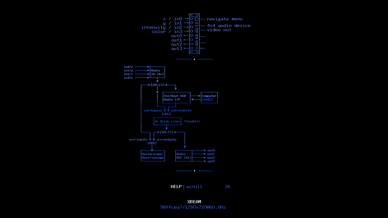
HELP page for XBEAM user bitstream.
Using Bitstreams
Note
The instructions here are always for the latest firmware - if the version shown at the bottom of the screen for any bitstream is not up-to-date (matching the latest version number / changelist here), I recommend updating! (instructions below)
Out of the box, Tiliqua ships with the following example bitstreams flashed. Many of them have built-in help pages. Here is a link to some more info on each one:
Warning
The documentation for each bitstream is not quite polished yet, but I hope there is enough material for you to be able to get started with the most important ones.
Jack LEDs
Normally, the Jack LEDs on each audio jack show the current voltage on the jack. However, whenever you are modifying an option or touching the encoder, the jack LEDs take on a different meaning.
This is because, in cases where you want to use a bitstream that has a menu system but don’t have space for a display (and are extremely dedicated and memorised the menu) it is possible to navigate purely based on the jack LEDs!
If jack LED is green: we are selecting a page. The jack LED number (0-7) is the page number.
If jack LED is red: we are selecting an option. The jack LED number (0-7) is the option index.
If the jack LED is flashing: we are in ‘modify’ mode. If it is not flashing, we are NOT in ‘modify’ mode.
The bar graph LEDs around the encoder show the currently selected option’s value on a scale from min (fully green) to max (fully red).
Touch Sensors
The capacitive touch sensors on each jack are calibrated when Tiliqua is turned on, and in some bitstreams (like POLYSYN), automatically re-calibrated every time a jack is plugged or unplugged. If you are having issues with ‘ghost’ touches, it’s often worth power cycling tiliqua with nothing patched on the jacks you want to use for touch sensing.
USB: the dbg and usb2 ports
For flashing bitstreams, you want the dbg USB port. This is routed to the on-board RP2040. For USB audio or USB device / host usage from bitstreams, you want the usb2 USB port. This is routed through a ULPI PHY directly to the FPGA fabric.
Note
If you are having trouble with the ``usb2`` port for USB audio streaming or as a MIDI host, I have collected some USB troubleshooting tips here.
Flashing/Updating Bitstreams
Tiliqua can be updated / flashed in 2 ways:
Use the tiliqua-webflash (LINK) tool, which works in any Chromium-based browser and allows you to flash bitstream archives to Tiliqua using any OS.
Using our
pdm flashcommand line tool, which requires setting up the Tiliqua development environment first. More details in Setup.
With tiliqua-webflash, the latest release is always shown - no need to download anything. For command line, you can find the latest published release here.
Tiliqua has 9 slots (bootloader + 8 user slots). Generally, you want to keep all of these up-to-date, however, as they are independent, you can have different versions of things in every slot. You’ll find instructions on how to update each slot in the respective flashing tool.
Note
Technical details for the curious! Tiliqua has 3 persistent memory chips that come pre-flashed out of the box. Flashing / updating bitstreams only touches the first one.
On the ‘Soldiercrab’: one 16MB SPI flash for the FPGA: This one contains the bootloader bitstream and all the user bitstreams, and any saved options.
On the ‘Motherboard’: 16MB SPI flash for the RP2040 / debugger: this one contains the debugger firmware used as a bridge between the
dbgUSB port and the FPGA JTAG.On the ‘Audio Board’: one small EEPROM for storing calibration constants, as well as the last entered bitstream used for autoboot. This contains the factory calibration.
Under the hood: updating or changing the bootloader bitstream or user bitstreams is performed using an open-source tool called openFPGALoader, as Tiliqua shows up as a dirtyJtag-compatible debug adapter. Bitstreams for Tiliqua are distributed as Bitstream Archives, which contain firmware and metadata alongside the bitstream itself. For technical details on how this works, see Bootloader).
Calibration
Tiliqua is shipped with a factory calibration to within 5mV or so. If you want to get even better, you can try to calibrate it yourself by following the calibration sequence here: Calibration
Warning
Before you conclude the NCO V/oct calibration is bad, note the calibration currently is only applied in bitstreams that have a menu system as reading the calibration uses a CPU. This limitation will be removed in a future update.
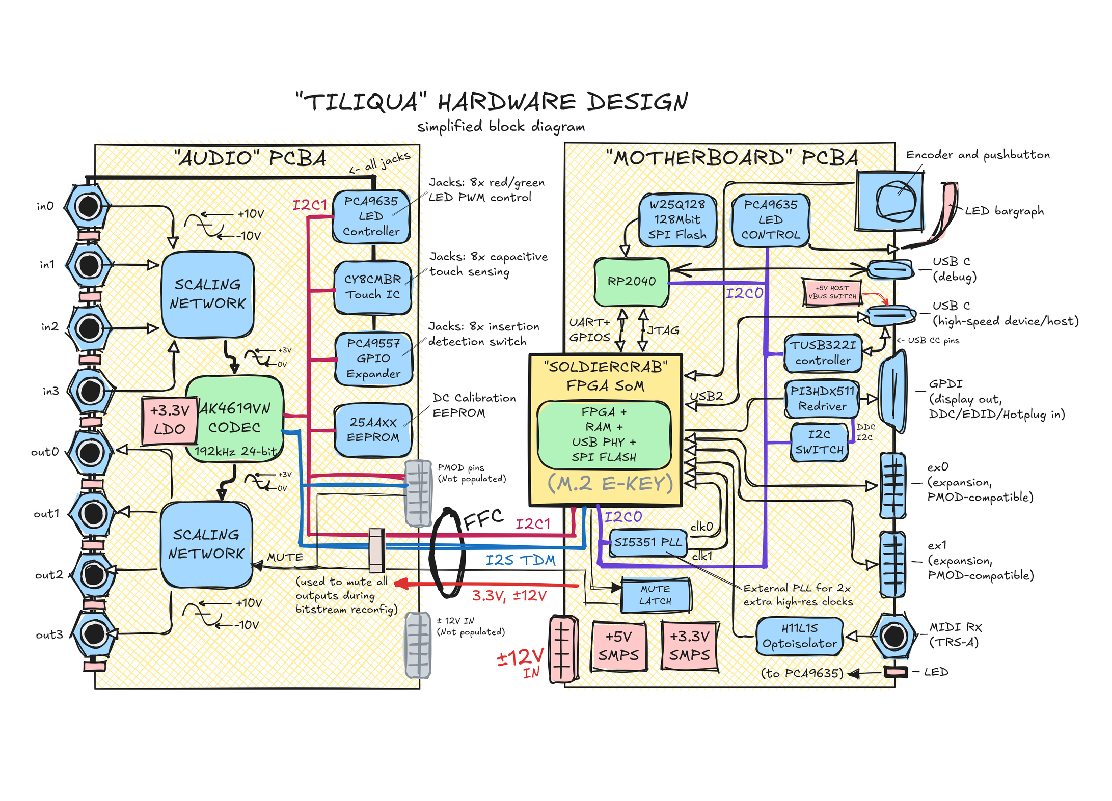
Hardware Block Diagram
For deeper details (and schematics) of the hardware, see Electrical Design
Instructions for Safe Use
The product shall only be used in a Eurorack system, providing a standard Eurorack power supply not exceeding +/- 12V, and at least 500mA. Any external case, power supply, cables, or modules shall comply with relevant regulations and standards applicable in the country of intended use.
To reach electromagnetic compatibility in a Eurorack system, the product shall be mounted securely in a fully enclosed housing made of conductive material (metal). Close all unused spaces with blind panels. Keep all cables, power or patch cables as short as possible.
The product should only be operated in a well ventilated case and should not be covered, except by the Eurorack case itself or other module panels. The product is designed for reliable operation at normal ambient room temperature. Do not expose the module to water, moisture or bring the circuit boards in contact with any conductive materials.
Take care whilst handling to avoid mechanical or electrical damage. When the product is powered on, do not touch any of the circuit boards behind the front panel. When the product is outside a case, only handle it unpowered and by the edges to minimize the risk of damage from electrostatic discharge.
Do not supply power to the product through any receptacle except the main +/- 12V power input. Any external devices not sharing the product’s main power bus (e.g. USB host devices or externally powered displays) should be disconnected when the product is unpowered. The incorrect usage or connection of unapproved devices to any receptacle may affect compliance or result in damage to the unit and invalidate the warranty.
Use of any firmware, gateware or clock frequencies not explicitly provided by the manufacturer is to be done at your own risk, in a controlled laboratory environment, with respect to relevant regulations and standards applicable in the country of intended use.